Motivation
Pumped-storage power plants can store energy on a large scale and with acceptable losses. They thus help reduce imbalances in the power grid and stabilize it. In recent years, the number of switches between pumped and turbine modes of operation has increased significantly. At IHS, simulation methods are being used within the framework of the EU project HYPERBOLE to investigate which flow phenomena occur during a rapid operating transition with constant guide vane opening. In order to later compare the measurement results, the investigations are applied to the operating parameters of a model turbine.
Background
Pumped-storage power plants have a storage reservoir both at the headwater and the tailwater. Depending on the direction of rotation of the machine, water is pumped up from below when there is a power surplus, or electrical energy is generated from the water flowing down from above when there is a power shortage. When switching between the operating modes, the direction of rotation of the machine must be reversed accordingly. In the project, first, the simplest case, a linear speed change from pump to turbine operation, is investigated.
Simulation
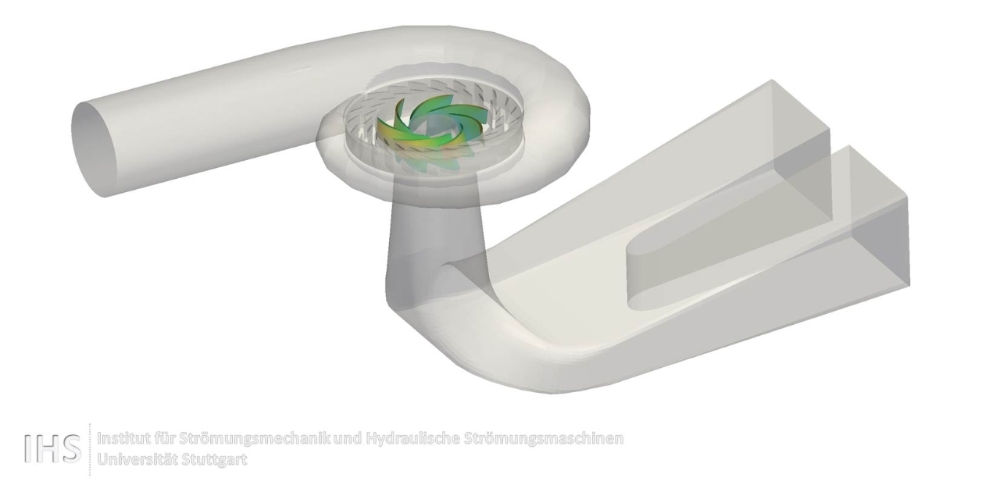
The calculations are performed with the open-source code OpenFOAM® and cover the machine as shown in Fig. 1 from the spiral to the suction pipe outlet. Variable conditions such as volume flow and speed can be specified via tables, which describe the time course of the parameters for the simulation.
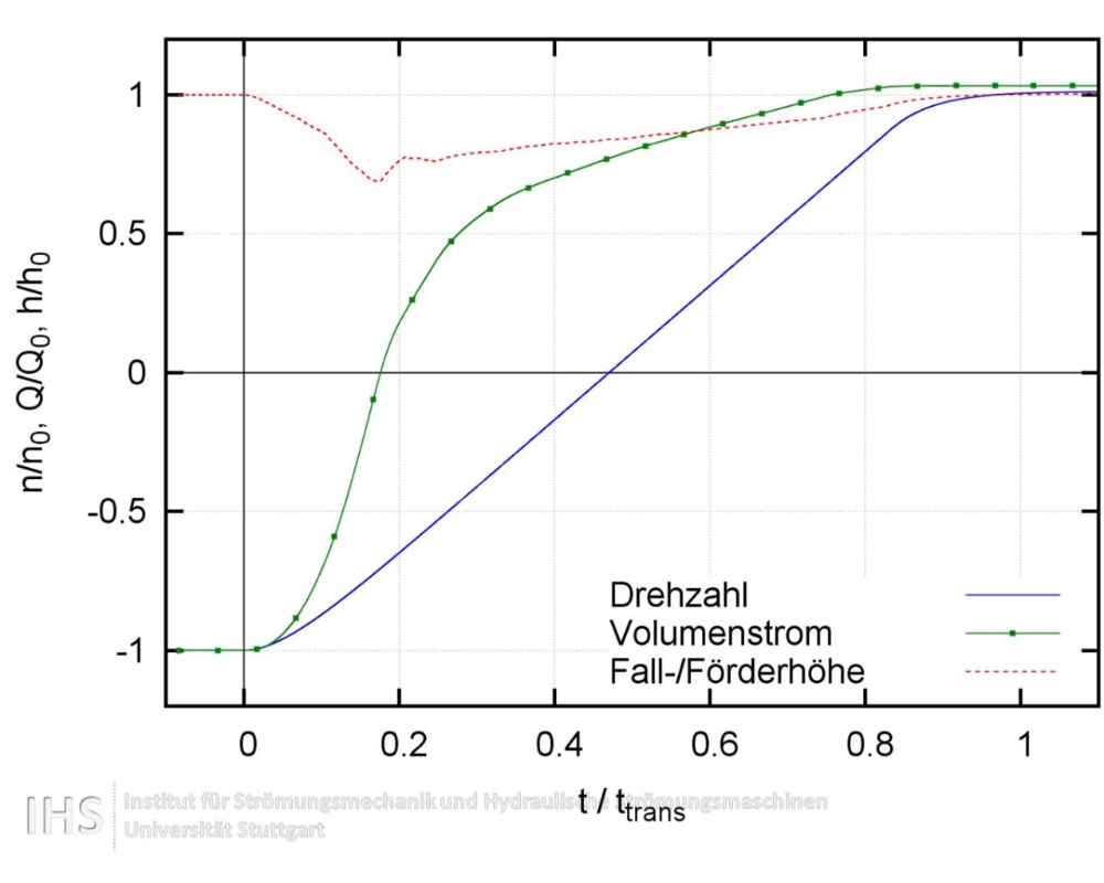
The specified speed of the machine as well as the design and operation of the test rig determine the volume flow that the simulation receives as a boundary condition. As Fig. 2 shows, the machine goes into pump-brake operation after less than 20% of the time, in which the water flows from top to bottom while the machine continues to rotate in the pump's direction.
Load on the blades
Under optimum conditions, the pressure of the water is distributed evenly over the respective blade side and over all the blades. However, because of the unusual operating conditions during an operational transition, this cannot be achieved and a considerable dynamic load is applied to the impeller.
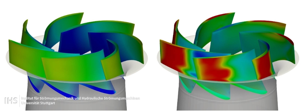
While the volume flow is reduced during the pumping operation, the flow at the guide vanes detaches. This leads to pressure fluctuations, which are particularly pronounced near the guide vanes on the pressure side of the blades. Even in pump-brake operation, this area remains highly stressed. As an example, Fig. 3 compares the pressure distribution on the guide vanes between a pump and pump-brake operation.
After reversing the impeller's direction of rotation, there are increased pressure fluctuations in the vicinity of the suction pipe. Here, the flow in the suction pipe still rotates in the "pumping direction" due to inertia, while the impeller is already rotating in the opposite direction. This gives rise to vortex structures that place a very uneven load on the impeller blades.
Financed by the Europian comission as part of the FP7-Project Hyperbole (ERC/FP7-ENERGY-2013-1-Grant 608532). Simulationipartly on ForHLR Phase I, financed by the Ministry of Science, Research, and the Arts and DFG as part of bwHPC.