Motivation
For the safe integration of renewable energies like photovoltaics, hydropower play an important role as it can be easily regulated. However, this comes across with the operation at off-design conditions that is accompanied by complex flow phenomena. One of these phenomena is cavitation which can cause severe damage in the turbine and can have a negative effect on the efficiency of the turbine. In the scope of the European Union project HYPERBOLE, the behavior of a Francis turbine at cavitating conditions was investigated for different operating points.
Fundamentals
Cavitation is defined as the evaporation of a liquid when pressure is falling below vapor pressure and the recondensation in regions where the pressure is above vapor pressure. Locally, very high pressures that can damage turbine components occur during the collapse of cavitation bubbles. The appearance of cavitation depends on the operating point and the pressure level in the turbine. Typically, no cavitation is present at design point.
Full load operating point
At full load operating point an axisymmetric vortex rope is forming in the draft tube cone (see Figure 1). The cavitation volume strongly depends on the pressure level. In model tests it is typically set by the pressure level in the downstream tank. In the real power plant the pressure level is defined by the water level of the downstream reservoir.
The developing vortex rope is stable over a wide operating range. However, for certain conditions a self-excited behavior can develop. This causes a pulsating vortex rope as it was investigated within the HYPERBOLE project. The dynamic behavior of the vapor volume is displayed in Figure 2. The collapse of the cavitation volume causes severe pressure peaks that can reduce the lifetime of the turbine. The unstable conditions of the self-excited behavior make it very challenging to perform numerical simulations of this operating point.

Deep part load operating point
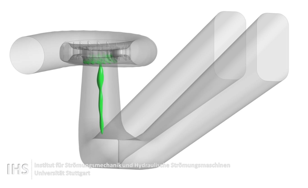
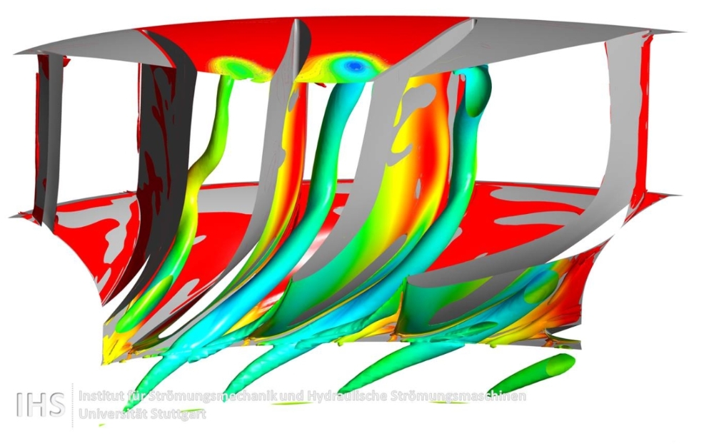
Starting from design point, a reduction of the discharge to a part load operating point results in a corkscrew shaped vortex rope. A further reduction of the discharge to deep part load leads to increased misaligned flow in the runner and inter blade vortices are developing in the runner channels. Figure 3 shows simulation results of the inter blade vortices at deep part load operating point.
Vortices are characterized by a pressure minimum in the vortex core. Especially for cavitating vortices it is important to properly resolve this pressure minimum. Therefore, fine computational grids of up to 50 million cells are necessary which causes a huge computational effort.
Finanziert von der Europäischen Kommission im Rahmen des FP7-Projekts Hyperbole (ERC/FP7-ENERGY-2013-1-Grant 608532).